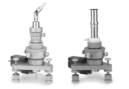
RS-200 Residual Stress Milling Guide | Micro-Measurements
The RS-200 Residual Stress Milling Guide is a critical tool for accurately measuring residual stresses using the widely recognized hole-drilling strain gage (gauge) method, as outlined in ASTM Standard E837. This practical and precise technique is essential for engineers and professionals involved in stress analysis, helping to ensure accuracy and reliability in their measurements.
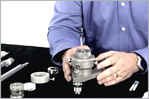
Watch a short RS-200 Video here.
How It Works:
- The hole-drilling strain gage (gauge) method involves bonding a specially configured electrical resistance strain gage (gauge) rosette to the surface of the test object. A small, shallow hole is then drilled through the center of the rosette.
- The local changes in strain caused by introducing the hole are measured, and from these measurements, the relaxed residual stresses are computed.
The Importance of Precision:
The accuracy and effectiveness of the hole-drilling method depend heavily on the precision of drilling the hole at the exact center of the strain gage (gauge) rosette. The Micro-Measurements RS-200 Milling Guide provides an easy-to-use, practical solution to ensure this high level of precision, directly contributing to the overall success of the stress measurement process.

Key Features:
- Precision Drilling: The RS-200 guide ensures that the hole is drilled with the highest accuracy, minimizing errors and enhancing the reliability of residual stress measurements.
- Practical Application: Specifically designed for use with the hole-drilling method, the RS-200 is ideal for professionals seeking dependable tools for stress analysis.
- Compatibility with ASTM Standards: Compliant with ASTM Standard E837, the RS-200 aligns with industry best practices, ensuring that your measurements meet recognized standards.
Elevate your residual stress measurement capabilities with the RS-200 Residual Stress Milling Guide from Micro-Measurements—your go-to solution for accurate, reliable stress analysis.
RS-200 Milling Guide Equipment
|
PART NUMBER |
DESCRIPTION |
|
|
|
|
MMP920-000265 |
RS-200 MILLING GUIDE- COMPLETE UNIT |
|
MMF336166 |
RS-200-CK2 GRIP ADHESIVE (5 PACK) |
|
REPLACEMENT PARTS |
|
|
|
|
|
MMF336166 |
RS-200-CK2 GRIP ADHESIVE |
|
MMP920-000193 |
RS-200-FP REPLACEMENT FOOT PADS QTY 3 WITH TEMPLATE |
|
MMP100-010569 |
RS-200 END MILL .062 |
|
MMP100-010573 |
RS-200 END MILL .125 |
|
MMP20X100033 |
RS-200-B1 REPLACEMENT BULB FOR LIGHTSOURCE |
|
MMP27X300006 |
ATC-200-062 CARBIDE-TIPPED CUTTERS (5/PKG) |
|
MMP27X300007 |
ATC-200-031 CARBIDE-TIPPED CUTTERS (5/PKG) |
Residual Stress Strain Gage Rosettes
|
GAGE PATTERN AND DESIGNATION |
RESISTANCE IN OHMS |
DIMENSIONS |
|||||||||||||
|
GAGE LENGTH |
GRID CTR’LINE DIA. |
TYPICAL HOLE DIA. |
MATRIX |
||||||||||||
|
Min. |
Max. |
Length |
Width |
||||||||||||
|
|
|
|
|
|
|
|
|
|
|
||||||
|
CEA-XX-062UL-120 |
|
120 ± 0.4% |
0.062 |
0.202 |
0.06 |
0.08 |
0.50 |
0.62 |
|||||||
|
1.57 |
5.13 |
1.5 |
2.0 |
12.7 |
15.7 |
||||||||||
|
Fully encapsulated with large copper-coated soldering tabs. Same pattern geometry as 062RE pattern. |
|||||||||||||||
|
CEA-XX-062UM-120 |
|
120 ± 0.4% |
0.062 |
0.202 |
0.06 |
0.08 |
0.38 |
0.48 |
|||||||
|
1.57 |
5.13 |
1.5 |
2.0 |
9.6 |
12.2 |
||||||||||
|
Fully encapsulated with large copper-coated soldering tabs and special trim alignment marks. Trim line spaced 0.068 in (1.73 mm) from hole center. Limitations may exist in data reduction equations. |
|||||||||||||||
|
EA-XX-062RE-120 EA-XX-062RE-120/SE |
 |
120 ± 0.2% 120 ± 0.4% |
0.062 |
0.202 |
0.06 |
0.08 |
0.42 |
0.42 |
|||||||
|
1.57 |
5.13 |
1.5 |
2.0 |
10.7 |
10.7 |
||||||||||
|
Most widely used RE pattern for general-purpose residual stress measurement applications. |
|||||||||||||||
|
EA-XX-031RE-120 EA-XX-031RE-120/SE |
|
120 ± 0.2% 120 ± 0.4% |
0.031 |
0.101 |
0.03 |
0.04 |
0.29 |
0.29 |
|||||||
|
0.79 |
2.56 |
0.8 |
1.0 |
7.4 |
7.4 |
||||||||||
|
Due to small pattern size, measurement error can be magnified by slight mislocation of drill hole. Pattern not recommended for general-purpose applications. |
|||||||||||||||
|
EA-XX-125RE-120 EA-XX-125RE-120/SE |
|
120 ± 0.2% 120 ± 0.4% |
0.125 |
0.404 |
0.12 |
0.16 |
0.78 |
0.78 |
|||||||
|
3.18 |
10.26 |
3.0 |
4.1 |
19.8 |
19.8 |
||||||||||
|
Larger version of the 062RE pattern. |
|||||||||||||||
|
|
|
|
|
|
|
|
|
||||||||
Related Products
|
GAK-2-200 Gage Installation Kit |
P3 Strain Indicator and Recorder |
H DRILL SOFTWARE |
Reference Documentation and Video:
B-127 Instruction Bulletin for Strain Gage Installations with M-Bond 200

TRAINING
Benefit from an extensive series of regularly scheduled, hands-on technical workshops and short courses.

HOW TO VIDEOS
We offer a wide variety of "How-To-Videos" hosted by expert application engineers. Step-By-Step training can be found here.

KNOWLEDGE BASE
Unlock a wealth of knowledge, from calculators to technical documents, to help you manage our strain gage (gauge) and PhotoStress® products.

RESOURCES
Learn about our stress analysis products, watch informative videos, and explore our large knowledge base.


